
| Copyright© by Barry Truax (Handbook for Acoustic Ecology). | ||
Electroacoustic technology is rich with terminology, some of which becomes quickly dated. Here we emphasize the most generic terms dealing with audio signals and the way in which they are recorded, manipulated and reproduced. The list should be thought of as more representative than comprehensive, with emphasis placed on the original meaning of the term in analog technology with comments on how the practical aspect has changed with digital technology.
Pertaining to or employed in the electronic transmission or reception of SOUND, such as in radio and television. The term is also used to refer to frequencies or signals in the audible range (see AUDIO FREQUENCY). Compare: INFRASONIC.
An audio signal refers to an ALTERNATING CURRENT signal or WAVEFORM which represents or is analogous to an acoustic signal, and which may be converted into an acoustic signal by means of a LOUDSPEAKER.
Compare: ACOUSTIC, AUDITORY, AURAL, ELECTROACOUSTIC, STEREOPHONIC. See also: SIGNAL.
Information being measured, transmitted or received via any medium. In terms of SOUND, it may be a sound to which one wishes to listen, or an electrical representation of a sound (audio signal) which is being recorded or reproduced (as with a MICROPHONE, TAPE RECORDER and MAGNETIC TAPE, or a disc recording), transmitted or broadcast (as with radio), or synthesized electronically or by means of a computer (see SOUND SYNTHESIS).
In any of these systems, the signal must be distinct from the NOISE (which is the opposite or complement of the signal) in order for information to be fully received. For instance, the television signal must be distinguishable from the 'snow' or interference, the sound signal on magnetic tape from the tape HISS. Although a DIGITAL RECORDING of information in the form of binary numbers may be regarded as a signal free of noise (but subject instead to errors or other forms of digital DISTORTION), if it represents a sound, it can only be heard if it is converted to an AUDIO SIGNAL.
See: BACKGROUND NOISE, CARRIER, CHANNEL, DROPOUT, FEEDBACK, PRINT-THROUGH, RADIO SPECTRUM, SEPARATION, SIGNAL-TO-NOISE RATIO, SWITCH, TRANSMISSION. Compare: communication, MESSAGE.
See SOUND SIGNAL for the use of this term in SOUNDSCAPE studies.
The most commonly used medium for recording sound. It is manufactured in various widths (1/4, 1/2 and one inch primarily) and thicknesses (3.0, 1.5, 1 and .5 mil where 1 mil = 1/1000 inch) for different purposes, which now include video and digital recording.
The tape is coated with an oxide EMULSION, which when exposed to the variations of the magnetic field at the recording head of a TAPE RECORDER, is arranged in similar variations, each particle of the emulsion having its own magnetic field, the direction and intensity of which indicates the SIGNAL's AMPLITUDE and FREQUENCY. See diagrams under EMULSION.
The most common backings used for tape are polyester and mylar (which stretch when subjected to a strong pulling force) and acetate (which breaks when pulled). Uncoated tape used to separate other sections of tape is called leader.
Magnetic tape superseded the earlier MAGNETIC WIRE recorders after World War II because of the ease with which one could SPLICE and therefore edit the tape.
See: TAPE LOOP, TAPE MUSIC, TAPE RECORDING.
The standard speeds at which analog tape recorders play the tape are 30, 15, 7-1/2 inches/sec (ips) in professional use (76, 38, 19 cm/sec respectively), and 7-1/2, 3-3/4 and 1-7/8 ips (19, 9.5, 4.75 cm/sec respectively) in normal home use. One, two, four or more CHANNELs or tracks of information can be stored on tape, the principal configurations of which are shown in the following diagram.
For some hazards of tape usage, see CROSSTALK, DROPOUT, FLUTTER, HISS, PRINT-THROUGH, WOW. See also: BULK ERASER, CUE, DEGAUSS, DUBBING, DYNAMIC RANGE, SEPARATION, TEMPOPHONE.
Standard tape recording formats for 1/4-inch analog tape as used by the Ampex Corporation. Dimensions listed are in mils.
DIGITAL RECORDING also uses magnetic tape as a storage medium, such as digital audio tape (DAT), but these smaller formats cannot be spliced. The tape speed for the DAT format is only 8.15 mm/sec because the tape head itself rotates at 2000 rpm in order to achieve its high bandwidth. When this format is referred to as RDAT, the R stands for 'rotary head'.
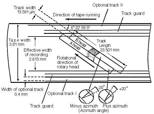
The structure of digital audio tape (DAT) and its head configuration..
An older medium of magnetic recording now superseded by MAGNETIC TAPE.
The magnetisable wire recorder was the first means of field recording and was used as early as 1899. The Danish engineer Valdemar Poulsen is credited with the development of methods by which sounds could be used to magnetize wire, steel tape or paper tape covered with metallic powder. The recordings could be erased and used again. Wire recorders, using stainless steel wires, were employed until the availability of iron oxide, plastic based tape in the late 1940s.
See: TAPE RECORDER, TAPE RECORDING. Compare: GRAMOPHONE, GRAPHOPHONE, PHONOGRAPH.
An early recording machine, like the GRAMOPHONE, capable of both recording and reproducing by means of the track-in-wax method on a cylindrical drum.
See: GRAPHOPHONE. Compare: MAGNETIC TAPE, MAGNETIC WIRE, TAPE RECORDER.
The early predecessor to modern record players which could record and reproduce sound, using a track-in-wax method on a flat disc.
Compare: GRAPHOPHONE, MAGNETIC TAPE, MAGNETIC WIRE, PHONOGRAPH, TAPE RECORDER.
Literally 'the pencil of sound.' An early name for the PHONOGRAPH.
A device for the quick removal of the recorded SIGNAL on an entire reel of MAGNETIC TAPE. The tape is exposed to a strong alternating magnetic field which removes the recorded signal. The device is also called a degausser.
See: DEGAUSS. Compare: diagram under EMULSION.
A discrete path or frequency BAND permitting the TRANSMISSION of MESSAGEs or SIGNALs. The width of the channel is usually restricted to accommodate just the types of signals employed in the messages, e.g. the telephone is restricted to the frequency band just necessary for the accurate comprehension of speech. The determination of channel capacity for information is studied in communication theory.
In TAPE RECORDING, the number of channels or tracks refers to the number of discrete signals which may be recorded at one time, as in MONOPHONIC, STEREOPHONIC, QUADRAPHONIC and other multi-track formats.
See: CROSSTALK, diagram under MAGNETIC TAPE, PAN, SEPARATION, SOUND-ON-SOUND.
When separate SIGNALs are recorded on two or more CHANNELs of MAGNETIC TAPE, or any other medium, the signal on one channel may be picked up during playback on another channel. This effect is called crosstalk or leakage.
Because of the close spacing of channels on tape, recorded signals cannot be completely separated during playback (even with the small space between the positions of the channels on tape), and thus some crosstalk is inevitable. However, its strength should be at least 60 dB less than that of the signal being monitored directly from a channel.
See: SEPARATION. Compare: CROSS-FADE, DROPOUT, PRINT-THROUGH, SPILL.
To locate a particular spot on a disc or tape prior to playback, or in the case of MAGNETIC TAPE, prior to editing. Also called scrubbing.
See: SPLICE. Compare: MONTAGE.
A momentary decrease in loudness noticed during MAGNETIC TAPE playback as the result of tape imperfections in the EMULSION which prevent close contact between tape head and tape being maintained during recording.
Compare: CROSSTALK, PRINT-THROUGH, SPILL.
A general term referring to the copying or transferring of audio material. Each time an analog copy (dub) is made, some quality is lost.
When an original source has been copied (i.e. dubbed) once, this copy is known as a first generation copy. A copy made from this first copy is called a second generation copy. With each successive generation, the quality of the original sound is reduced and the BACKGROUND NOISE is increased. This problem occurs only with analog audio signals, as stored on MAGNETIC TAPE, for instance, and not at all in DIGITAL RECORDING as long as the copy is error-free.
See: HISS, PRESENCE, SIGNAL-TO-NOISE RATIO. Compare: MIXING, SOUND-ON-SOUND.
The oxide coating on MAGNETIC TAPE, composed of microscopic magnetizable particles suspended on a plastic film base or backing, such as acetate, polyester or mylar. During recording, the particles are re-aligned in correspondence with the input signal, and later during playback, these particles (also called domains) induce a similar current which reproduces the original signal. Tape without emulsion is called leader tape.
See: BULK ERASER, DEGAUSS, DROPOUT, TAPE RECORDER.

The structure of magnetic recording tape.

Realignment of magnetized particles during the recording process.
In recording or reproducing sound, a rapid fluctuation in speed, and therefore PITCH, that creates a warble-like effect. It is usually caused by a fault in the drive mechanism of analog recording or reproducing equipment. The rate of flutter is faster than that of WOW, and is usually 8 kHz or more.
Compare: FREQUENCY MODULATION, GLISSANDO, TAPE RECORDER, TREMOLO, VIBRATO.
A term borrowed from film terminology and referring to sequences of sounds which are mixed or edited together sequentially.
Compare: CROSS-FADE, CUE, MIXING, SPLICE.
When an analog SIGNAL stored on MAGNETIC TAPE is partially transferred to the section of tape adjacent to it on a reel, the result is called print-through and is heard as a pre-echo. Thin tape, particularly when stored for a long time without being rewound or played, is highly susceptible to this problem. Storing tapes 'tail out' is recommended to minimize the effect of print-through. Also called signal transfer, or printing.
Compare: CROSSTALK, DROPOUT, SEPARATION, SOUND-ON-SOUND, SPILL, TAPE ECHO.
The degree to which the SIGNAL received by a microphone or that stored on one CHANNEL of a STEREOPHONIC or QUADRAPHONIC recording or disc is kept separate from any other signal on the same recording. With analog tape, the physical distance between the recorded channels is maximized (see digram under MAGNETIC TAPE).
The amount of separation is measured in DECIBELs, and represents the degree to which signals have been kept separate during the recording or MIXING process. Quadraphonic disc recordings rarely achieve over 25 dB separation, whereas with tape, 50 dB can easily be achieved. Good separation is often called discrete channeling, but the degree of discreteness implied is uncertain unless a decibel measurement is also given.
Compare: CROSSTALK, DICHOTIC, PRINT-THROUGH, SPILL.
To join two ends of MAGNETIC TAPE by means of an adhesive material called splicing tape which is usually slightly narrower than the tape itself. As a noun, it refers to a join (also called a joint in Britain) made in this way.
The join is usually at the 45° diagonal, and sometimes at 90° (butt splice). Improperly made splices, or those made with magnetized scissors or razor blades, may result in CLICKs.
Splicing is used for editing taped material, creating TAPE LOOPs, controlling the ATTACK or DECAY portion of a sound ENVELOPE, isolating SOUND OBJECTs for study, or for the compositional manipulation of sound as in TAPE MUSIC.
Newer forms of tape used to record digital audio or video material cannot be spliced, and therefore all editing must be done electronically. See: DIGITAL RECORDING.
A segment or sequence of segments of MAGNETIC TAPE which have been SPLICEd end-to-end to form a loop or circle. When played in this form, the taped sound is continuously repeated, as distinct from tape ECHO or tape FEEDBACK.
Compare: DRONE, STATIONARY SOUND.
A tape loop may serve to isolate a SOUND OBJECT, allowing analysis of its ENVELOPE or SPECTRUM, for instance. In TAPE MUSIC and MUSIQUE CONCRETE, tape loops are often employed to create a rhythmic or timbral effect, particularly when played at speeds other than the normal one.
The period of repetition of the loop depends both on its length and the speed at which it is played, being equal to the length divided by the speed. See also: TAPE RECORDER.
Digital audio systems designed for editing often allow sequences of samples to be played repetitively, thus simulating a tape loop, and some offer techniques for minimizing any discontinuity in the waveform (heard as a CLICK) at the splice point.
A slow fluctuation in PITCH due to mechanical faults in analog recording or reproducing equipment. The rate of wow is slower than that of FLUTTER, and is usually in the range of 1-5 Hz.
With sustained or slow moving sounds, wow can be detected as a slow OSCILLATION of pitch when the frequency variation is about 0.25%. With shorter sounds, the ear can only detect much greater variations.
Compare: FREQUENCY MODULATION, RUMBLE, TAPE RECORDER, VIBRATO.
A device used with MAGNETIC TAPE in order to vary either the PITCH or TEMPO of recorded information but not both variables together. Normally with tape playback, a change of speed or tempo produces an equivalent change in pitch, but with this device the two variables may be treated independently.
The basic principle of the machine, first developed in Germany, depends on the relative direction and speed of the tape and that of multiple playback heads mounted on a rotating cylinder. The tape passes over the heads such that only one head is in contact with the tape at any one time, since the moment one head leaves the tape, a second head has rotated into position to continue contact.
If the rotating heads are moving in the same direction as the tape, the resulting pitch will be lower without affecting the tempo, whereas if the heads are rotating in the opposite direction of the tape, a higher pitch results. The principle is similar to that of the DOPPLER EFFECT which depends on the relative speed of sound source and listener.
The machine has a variety of uses, from simple adjustment of TUNING to the creation of new sounds with timbral or durational characteristics that are normally impossible. A variety of names apply to the device: the original German zeitdehner (literally, 'timestretcher'), as well as tempo regulator, pitch regulator and information rate changer, or simply rate changer. Compare: TAPE RECORDER.
Today, various digital techniques, such as granulation, that "window" and overlap short durations of sound perform operations similar to those of the tempophone such as time stretching.
A device for transforming or converting power from one form to another. Thus, a MICROPHONE is a transducer which converts variations of SOUND PRESSURE into variations of electrical current, and a LOUDSPEAKER is a transducer which performs the reverse function. Such devices are termed ELECTROACOUSTIC.
See: DIAPHRAGM. Compare: AMPLIFIER, GENERATOR, LIMITER, RECEIVER, RECTIFICATION.
The equivalent device for changing audio signals to digital form and back is called a converter. See: DIGITAL RECORDING, SOUND SYNTHESIS.
Another type of transducer is the accelerometer which reacts to the acceleration (rate of change of velocity) of a surface to which it is attached, producing an equivalent electrical signal.
The EAR itself may be regarded as a complex non-LINEAR transducer in that it converts acoustic energy into electrical impulses in the INNER EAR. See: BASILAR MEMBRANE.
An ELECTROACOUSTIC TRANSDUCER which converts variations in SOUND PRESSURE into an equivalent electrical SIGNAL, which then may be fed to a TAPE RECORDER or other electronic equipment. Abbreviation: mic (pronounced 'mike').
The major types of microphones, each with its own type of DIAPHRAGM, are:
Various types of microphones are designed with sensitivity characteristics that vary with the direction of the source. This pattern of sensitivity is called the DIRECTIVITY, directional characteristic or field pattern. See DIRECTIVITY for a list and diagrams and STEREOPHONIC for further discussion.
See also: ACOUSTIC FEEDBACK, BAFFLE, BINAURAL RECORDING, DIGITAL RECORDING, KUNSTKOPF, PARABOLIC REFLECTOR, SPILL, WIND SCREEN. Compare: LOUDSPEAKER.
A TRANSDUCER which converts electrical energy to acoustical energy. Very often, loudspeakers with different FREQUENCY RESPONSE characteristics are combined together in a speaker system. This is necessary for HI-FI reproduction, since it is difficult for a single loudspeaker to reproduce the entire audio spectrum.
Loudspeakers which reproduce low frequencies are called WOOFERs; those which reproduce high frequencies TWEETERs.
See: ACOUSTIC RADIATION, BAFFLE, DIAPHRAGM, DIRECTIVITY, ELECTROACOUSTIC, ENCLOSURE, PAN, SUBHARMONIC, TRANSIENT RESPONSE. Sound examples under FREQUENCY RESPONSE. Compare: MICROPHONE.
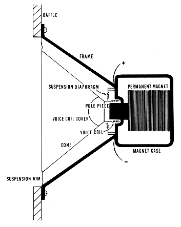
Components of a typical loudspeaker mounted on a baffle.
A shielding structure used to increase the effective length of the external path between two points in an acoustic system. For instance, in studio recording, a baffle, or FLAT, may be used to separate performers, and in an auditorium, baffles may be used to achieve better sound DIFFUSION and REFLECTION.
The most common use of the term is to refer to the material surrounding a LOUDSPEAKER. In the simplest case, this is a piece of wood on which the speaker is mounted to prevent sound waves from escaping around the edges. The aim is to avoid CANCELLATION between the sound waves produced at the front and rear of the speaker which have a PHASE DIFFERENCE of 180° due to the back and forth motion of the speaker DIAPHRAGM.
When the distance between front and rear is less than a quarter WAVELENGTH, the FREQUENCY RESPONSE falls off because of cancellation. More complex baffles, such as the bass reflex baffle, can be designed to surround the speaker and improve low frequency response.
See: ENCLOSURE, WOOFER, and diagram under LOUDSPEAKER.
A LOUDSPEAKER cabinet. Its most important function is to improve BASS response by forcing the sound waves produced at the rear half of the loudspeaker:
A high frequency LOUDSPEAKER or cluster of speakers, usually arranged in the form of a fan, to assist the adequate dispersion of high frequency sound with shorter WAVELENGTHs.
See: DIFFRACTION. Compare: TREBLE, WOOFER.
Low frequency unit in a LOUDSPEAKER.
See: BAFFLE, BASS, ENCLOSURE. Compare: TWEETER.
One of the parts of a TRANSDUCER involved in the conversion of mechanical energy to electrical energy, or vice versa.
The diaphragm is the membrane whose physical motion corresponds to the acoustical vibration being received or emitted; for instance, the part of a MICROPHONE on which the pressure of the SOUND WAVE acts, or the part of a LOUDSPEAKER activated by electrical energy to produce an acoustic vibration. Diaphragms serve a similar purpose in air horns, car horns and the like. See LOUDSPEAKER for diagram.
A light rigid structure (of aluminum or other material) which reflects sound to a focus at which a MICROPHONE is placed. This focussing effect is very strong with WAVELENGTHs less than the aperture of the reflector, making it particularly suitable for recording high frequency sounds such as birdsong.
Compare: DIRECTIVITY, DIFFRACTION, REFRACTION, SHOTGUN MICROPHONE.

Schematic diagram of a parabolic reflector. Incoming sound is directed to the microphone placed at the focus of the parabola-shaped reflector.
The property of the parabolic shape to reflect all sound symmetrically results in multiple REFLECTIONs known as 'slap echoes' when larger structures have this shape.
 Sound
Example: Multiple ECHOes produced
under a parabolic bridge, Stanley Park, Vancouver, B.C. The source sound is a
stick hitting a metal can.
Sound
Example: Multiple ECHOes produced
under a parabolic bridge, Stanley Park, Vancouver, B.C. The source sound is a
stick hitting a metal can.
In recording, sound being picked up by any MICROPHONE other than that intended.
Compare: ACOUSTIC FEEDBACK, CROSSTALK, PRINT-THROUGH, SEPARATION.
A protective covering for a MICROPHONE designed to reduce wind noise, which is mainly low frequency and INFRASONIC in character. Also called a windshield.
(Greek: monos = one; phone = sound) A form of reproduction which records, transmits and reproduces the original sound along a single CHANNEL, regardless of the number of loudspeakers used. All components of the sound are combined or MIXed into one SIGNAL, including AMBIENCE and REVERBERATION, and therefore only the sense of depth may be simulated or reproduced (see PROJICIENCE).
The lack of spatial spread may make it difficult to distinguish separate sounds (compare COCKTAIL PARTY EFFECT). Monophonic sources may be treated spatially when more than one channel is used, as described under STEREOPHONIC. Also called mono or monophonic sound.
Compare: BINAURAL RECORDING, DICHOTIC, MONAURAL HEARING, QUADRAPHONIC, STEREOPHONIC.
A form of STEREOPHONIC or multi-channel reproduction in which the sound source is spread around the listener by the use of four tracks or CHANNELs in recording or transmission and the use of four (or more) LOUDSPEAKERs. Conventional music or speech may be recorded in this way, in which case the speakers behind the listener add REVERBERATION to the original sound or are simply out of PHASE with respect to the front ones; or new works may be composed in which all tracks carry original material.
Commercially, quadraphonic sound became available about 1970. However, it has been in use in Europe for ELECTRONIC MUSIC since the 1950s. Today, eight-channel or octophonic systems have superseded quadraphonic ones.
Compare: MONOPHONIC, STEREOPHONIC. See also: ACOUSTIC SPACE, DIFFUSION, KUNSTKOPF. Also spelled quadriphonic.
An electrical network used to reduce the input SIGNAL to a device such as an AMPLIFIER. The simplest variable attenuator is the POTENTIOMETER, or potential divider, which varies the input continuously by adjusting the position of a sliding contact.
See: ATTENUATION, FADER. Compare: FILTER.
Generally, a device in which some characteristic of its output is automatically prevented from exceeding a certain value. In particular, a TRANSDUCER in which the AMPLITUDE of the output is LINEAR with respect to the input up to a predetermined value, and constant thereafter.
The device is used in commercial radio transmission and in popular recording techniques to avoid distorting respectively the outgoing or incoming signal, and therefore to keep the signal within the DYNAMIC RANGE of the system.
See: COMPRESSION, DISTORTION, MODULATION. Compare: PEAK CLIPPING, TRANSIENT RESPONSE.
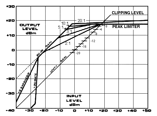
Relation of input to output levels in a compressor, limiter and expander. The limiter is shown as a horizontal line indicating that the output signal cannot exceed a certain level, regardless of the input level.
The frequencies or PITCHes in a low RANGE, usually undefined as to the specific limits implied. Opposite of TREBLE. In music it refers to the lowest singing range, or any instrument playing a low-pitched part, as well as the lowest musical part itself.
Many amplifiers intended for home use have one control marked 'bass' which alters the GAIN given to lower frequencies. However, such a simple control does little to improve sound FIDELITY in any meaningful way, and is more generally used to eliminate HUM in poorly grounded equipment, or to exaggerate low frequencies with certain types of music.
See: ENCLOSURE, EQUALIZATION, FLAT, RUMBLE, WOOFER. Compare: INFRASONIC.
The frequencies or PITCHes in a high RANGE, usually undefined as to the specific limits implied. Opposite of BASS. In music it refers to the highest part in a choral piece.
Many amplifiers intended for home use have one control marked 'treble', which alters the GAIN given to higher frequencies. However, such a simple control does little to improve sound QUALITY in any meaningful way, and is more generally used to eliminate HISS on equipment with poor FREQUENCY RESPONSE and SIGNAL-TO-NOISE RATIO. Also called top.
See: EQUALIZATION, FLAT, TWEETER. Compare: SIBILANCE.
An electrical device used to affect certain parts of the SPECTRUM of a sound, by causing the ATTENUATION of certain frequency BANDs, while allowing other bands to pass unattenuated. Some common types of filters are:
A group of such filters may be interconnected to form a filter bank.
See: COMB FILTER, EQUALIZATION, MASS, SOUND ANALYSER. For the use of filters in ELECTRONIC MUSIC, see MUSIQUE CONCRETE, SOUND SYNTHESIS, SOUND SYNTHESIZER.
The BANDWIDTH of the spectrum which is passed unattenuated depends on the cut-off frequency, that is, the lowest or highest frequency attenuated less than 3 dB. For an ideal filter, the attenuation for frequencies beyond the cut-off would be complete, but in practice each filter has a gradual reduction, or roll-off, which is measured as the rate of attenuation for frequencies beyond the cut-off, in decibels/octave (6 dB/octave is considered minimally acceptable). The unattenuated range of a filter is called its passband.
The Q of a bandpass filter is a measure of its RESONANCE and is defined as the ratio of CENTRE FREQUENCY to the bandwidth. The narrower the bandwidth, the higher the Q, and the more the filter will 'ring' or go into oscillation when stimulated by a signal with energy near the centre frequency. A constant Q filter varies its bandwidth as a function of the centre frequency, always keeping the ratio between them the same. Compare: CRITICAL BANDWIDTH.

Generalized response characteristic of a band-pass filter. A low-pass filter includes only an upper cut-off, and a high-pass filter only a lower cut-off frequency. A band-reject filter has the inverse characteristic of that shown.
Sound
Example: Four examples of filtered
white noise:
The standard correction which is made during disc and tape recording or playback with regard to the FREQUENCY characteristics of the sound SIGNAL. This correction emphasizes some frequency BANDs in the SPECTRUM of a sound and de-emphasizes others. The process is also called compensation.
Equalization according to standard curves as shown below establishes the FREQUENCY RESPONSE characteristics for recording and playback of phonograph discs and magnetic tape. The recording characteristic is always the inverse of that of the playback; for example, high frequencies are boosted during disc recording by the same amount that they are attenuated during playback, thus resulting in FLAT response for the entire operation. 0 dB is set as the output at 1 kHz.
The curves for phonograph recording and playback, adopted in the U.S. and Great Britain in 1953, are known as the RIAA curves of standard equalization. The NAB and RIAA curves for tape recording (which operate in the opposite sense of those for disc with respect to frequency) are also shown. These characteristics are those of the pre-amplifier in most TAPE RECORDERs.
Besides standard equalization, other devices called equalizers, which are often built into mixers, are designed to perform a similar function on different parts of the audio spectrum. Those that are termed active can boost or attenuate (by ± 6 - 12 dB) bands, such as that around 10 kHz (to attenuate HISS or emphasize high frequencies), in the 2 - 4 kHz range (to improve PRESENCE) or those around 100 Hz (to control low frequencies or RUMBLE). The shelving type equalizer boosts or attenuates all frequencies above a specific high frequency, or below a specific low frequency.
Although some equalizers resemble FILTER banks, they differ in that only a limited range of AMPLIFICATION or ATTENUATION is possible. Equalizers are often identified by their CENTRE FREQUENCY (see chart under SOUND ANALYSER) and BANDWIDTH, such as 1/3 - octave, 1/2 - octave, full octave, and so on.
Controls marked TREBLE and BASS on amplifiers perform a similar function, but are more properly termed tone controls because they can only attenuate low or high frequencies respectively while boosting the entire signal level.
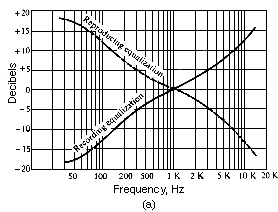

Effect of equalization networks on audio-amplifier frequency response: (a) standard RIAA recording and playback characteristics for phonograph records; (b) standard playback equalization characteristics for tape recorders (from Herrick, Instruments and Measurement for Electronics, McGraw-Hill, 1972, used by permission).
An audio WAVEFORM theoretically comprised of an infinite set of HARMONICally related SINE WAVEs, as shown under LAW OF SUPERPOSITION. It is often used in SOUND SYNTHESIS.
See also: FOURIER THEOREM, OSCILLATOR. Compare: PULSE, SQUARE WAVE, TRIANGLE WAVE.

Sawtooth wave, its description as a Fourier series, and as a line SPECTRUM.
Sound
Example: Sawtooth wave at 100 Hz.
An audio WAVEFORM theoretically comprised of an infinite set of odd harmonic SINE WAVEs. It is often used in SOUND SYNTHESIS.
See also: FOURIER THEOREM, LAW OF SUPERPOSITION, OSCILLATOR, SWITCH. Compare: PULSE, SAWTOOTH WAVE, TRIANGLE WAVE.
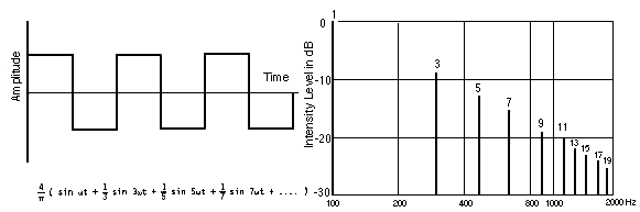
Square wave, its description as a Fourier series, and as a line spectrum.
Sound
Example: Square wave at 100 Hz.
Also, triangular wave. An audio WAVEFORM theoretically comprised of an infinite set of odd harmonic SINE WAVEs. It is often used in SOUND SYNTHESIS where its TIMBRE is less harsh than the SQUARE WAVE because the amplitude of its upper HARMONICs falls off more rapidly.
See: FOURIER THEOREM, OSCILLATOR. Compare: PULSE, SAWTOOTH WAVE.

Triangular wave, its description as a Fourier series, and as a line spectrum.
Sound
Example: Triangle wave at 100 Hz.
In recording and broadcasting, bringing a voice or instrument into the foreground (i.e. raising it out of AMBIENT sonic environment) by emphasizing its components, particularly in the 2-4 kHz range where the ear is most sensitive. See: EQUAL LOUDNESS CONTOURS.
Colloquially, any sound is said to have 'presence' when it stands forward clearly. Tape recorded sounds that have been DUBbed many times often lack presence because of signal degeneration.
See also: EQUALIZATION. Compare: FIDELITY, HI- FI, LO-FI, QUALITY, SONORITY.
Sound
Example: Recorded speech, heard first with an attenuation of the
energy in the presence range (simulating poor recording quality), followed by a
boost in that same range.
The ratio of the magnitude of the wanted SIGNAL to that of the unwanted NOISE, expressed as a simple arithmetic ratio or in DECIBELs. For example, the ratio between the input signal and the system noise of an amplifier. Also abbreviated S/N.
See: BACKGROUND NOISE, DIGITAL RECORDING, DYNAMIC RANGE, TAPE RECORDING. Compare: GAIN, VU METER.
A signal-to-noise ratio is said to be favorable when the signal predominates; that is, it can be clearly distinguished from the noise, and exceeds it by at least 60 dB. When signal and noise are less clearly distinguishable, the signal-to-noise ratio is said to be poor or low.
See: ACOUSTIC SPACE, HI-FI, LO-FI. Compare: COCKTAIL PARTY EFFECT.
(Latin: fidelis = faithful) The faithfulness, or extent of the correspondence, of a reproduced sound to the original sound; by implication, it is used loosely to describe sound QUALITY and the absence of DISTORTION.
See: ELECTROACOUSTIC, FREQUENCY RESPONSE, HI-FI, LO-FI. Compare: PRESENCE, SCHIZOPHONIA.
Abbr. for high-FIDELITY, that is, a system reproducing a full audio frequency SPECTRUM (20 to 20,000 Hz) and a favourable SIGNAL-TO-NOISE RATIO. The most general use of the term is in ELECTROACOUSTICs, such as when applied to an AMPLIFIER or a recording.
Compare: QUALITY, PRESENCE. See also: DYNAMIC RANGE.
In terms of SOUNDSCAPE studies, the hi-fi environment is one where all sounds may be heard clearly without being crowded or MASKed by other sounds and NOISE.
Compare: LO-FI. See: ACOUSTIC SPACE, CLAIRAUDIENCE, FEEDBACK, SOUND EVENT, SOUNDWALK.
Sound
Example: A piazza in Cembra, Italy, with voices and footsteps in the
foreground, a more distant church bell, and a choir from another church in the
middle ground.
Sound Example: A DC elevator in an old building in Vancouver. Note the absence of electrical hum.
Abbr. for low-FIDELITY, that is, a system which reproduces less than a full frequency SPECTRUM, and which has a poor SIGNAL-TO-NOISE RATIO. The most general use of the term is in ELECTROACOUSTICs, such as when applied to an AMPLIFIER or recording. See SCHIZOPHONIA for sound examples.
In terms of SOUNDSCAPE studies, the lo-fi environment is one in which signals are overcrowded, resulting in MASKing and lack of clarity.
Compare: HI-FI, PRESENCE. See: ACOUSTIC HORIZON, ACOUSTIC SPACE, FEEDBACK, MOOZAK, NOISE POLLUTION, REVERBERATION, REDUNDANCY, SOUND EVENT, SOUND POLLUTION.
Sound
Example: Urban traffic ambience.
Sound Example: Outdoor ambience, University of British Columbia, with construction noise.
Sound Example: Competing background music from shops along Carnaby Street, London.
This term refers to changes of a sound WAVEFORM which occur in ELECTROACOUSTIC systems. It can also refer to certain non-LINEAR effects in the inner ear.
See: AURAL HARMONICS, COMBINATION TONES, DIPLACUSIS, RECRUITMENT. Compare: FIDELITY.
Problems in an electroacoustical system which produce distortion are the following:
In ELECTRONIC MUSIC and some kinds of modern popular music, distortion is exploited for musical purposes. The composer may alter the waveform of the original sound by various MODULATION techniques. The rock group often creates distorted effects by means of FEEDBACK or by overloading the amplifiers and speakers.
See also: FLUTTER, LIMITER, MIXING, MODULATION, OSCILLOSCOPE, VU METER, WOW.
Sound
Example: Peak clipping of a sine wave when raised beyond the overload
point of an analog mixer.
(Greek: schizo = split; phone = voice, sound) The term was first employed by R.M. Schafer in The New Soundscape (Toronto, 1969, pp. 43-47) to refer to the split between an original sound and its ELECTROACOUSTIC reproduction in a SOUNDSCAPE.
Original sounds are tied to the mechanisms which produce them. Electroacoustic sounds are copies and they may be reproduced at other times or places. Schafer employs this 'nervous' word in order to dramatize the aberrational effect of this twentieth century development.
See: MOOZAK, LO-FI, SOUND INTRUSION, SOUND POLLUTION, TAPE RECORDER. Compare: FIDELITY, SOUND PHOBIA, SOUNDSCAPE DESIGN.
Sound
Example: Recording of Gordon MacRae played from the bell tower of a
church in Hanley, Saskatchewan.
Sound Example: Amplified voice at a fast food restaurant in Halifax, N.S.
Sound Example: Amplified voice from a mobile public address system.
Sound Example: Amplified voices at the Atlantic Winter Fair, Halifax, N.S.
Sound Example: Background music at a shopping mall.
The DISTORTION caused when the GAIN of an amplifier is increased to a point where the high points, or peaks, of the SIGNAL or WAVEFORM are cut off at a level where the amplifying circuits are driven beyond their overload point. Also called over-MODULATION.
Peak clipping may be avoided by gain reduction, COMPRESSION of the signal, or by the use of a LIMITER.
Compare: RECTIFICATION, SWITCH.

Positive and negative clipping of a sine wave.
Sound
Example: Peak clipping of a sine wave when raised beyond the overload
point of an analog mixer.
Used primarily in broadcasting and recording, fade refers to the gradual increase (fade-in) or decrease (fade-out) of a SIGNAL, usually accomplished with a FADER or POTENTIOMETER.
See: CROSS-FADE, MIXING, MONTAGE. Compare: ATTENUATION, PAN.
In broadcasting and studio MIXING, a cross-fade is the simultaneous occurrence of a fade-in (of new material) and a fade-out (of old material), usually lasting 1 - 5 seconds.
See: FADE. Compare: CROSSTALK, MONTAGE, PAN.
Sound
Example: A slow cross-fade between a restaurant with a prominent
electrical hum, and a humming power line, several thousand miles away, both of
which have the frequency of
ALTERNATING CURRENT in common.
Any device in which the position of a knob, dial, slide or lever controls the output level or GAIN of a signal, such as on a mixer or amplifier. Also called a potential divider, FADER or ATTENUATOR.
A POTENTIOMETER used to make a FADE. Compare: ATTENUATOR.
The RESPONSE of a system is linear when the output is directly proportional to the input, that is, any change in the input produces a proportional change in the output. When plotted on a graph, a straight line results.
A non-linear system is one where such a proportional relationship between input and output does not hold, as shown in the corresponding graph.

Linear and non-linear relationships (a, b). Graphs (c, d) show a HARMONIC SERIES spectrum with two different scales on the horizontal axis. With (c) the frequency axis is linear, whereas with (d) the scale is logarithmic, with the result that octave intervals are equidistant and the harmonics are spaced increasingly closer. See: BASILAR MEMBRANE.
The result of the non-linear characteristics of the ear is the addition of harmonics when the incoming sound is of sufficient intensity.
See: AURAL HARMONICS, COMBINATION TONES, DISTORTION, HETERODYNE, LAW OF SUPERPOSITION, MIXING.
Frequency, for instance, although it is a continuously variable PARAMETER, is not linear with respect to PITCH, since equal changes in frequency do not result in equal pitch changes. Instead, frequency must be doubled to get equal pitch changes, and therefore the relation may be called logarithmic (see MEL; for loudness, see DECIBEL, PHON, SONE).
With audio signals, linearity in their amplification is desirable, but when the signal has a large DYNAMIC RANGE, a LIMITER must be used to prevent overload and distortion, and in other cases, non-linear amplification called COMPRESSION must be used to reduce the signal's dynamic range.
In SOUND SYNTHESIS, non-linear techniques such as MODULATION are used to produce rich spectra from simpler sources.
Whenever a PARAMETER of a sound or audio SIGNAL called the CARRIER is varied systematically, the signal is said to be modulated. The signal whose WAVEFORM is being used to control the carrier is called the modulator or program signal. Modulation is a standard technique for both radio TRANSMISSION and SOUND SYNTHESIS, although the frequencies used are in very different RANGEs. See: RADIO SPECTRUM.
Three common types of modulation are FREQUENCY MODULATION, AMPLITUDE MODULATION, and ring modulation, all of which are non-LINEAR approaches to sound synthesis.
Modulation at AUDIO rates (i.e. greater than 20 Hz) produce audible SIDEBANDs. Modulation at SUBAUDIO rates (i.e. less than 20 Hz) produce effects such as TREMOLO and VIBRATO.
See: GRAIN, HETERODYNE, MODULATED CARRIER, MODULATION DEPTH, periodic.
Sound
Example: Amplitude modulation.
Sound Example: Frequency modulation.
Sound Example: Ring modulation, where the sidebands are the sum and difference of the two inputs, one of which is held constant at 100 Hz, the other swept from 0 Hz to 300 Hz.
Modulation also refers to the signal LEVEL on a recording, transmission or reproduction system. Full modulation or 100% modulation refers to the maximum permissible (i.e. distortion-free) level of such a system. Many radio stations design their signals to ride near full modulation a great deal of the time by means of compression (see diagrams under COMPRESSION).
Over-modulation occurs when this maximum level is exceeded, and the result is DISTORTION, or even equipment damage. LIMITERs are used to prevent over-modulation and PEAK CLIPPING. Percentage of modulation is measured on a VU METER. See: ZERO LEVEL VU.
In music, modulation refers to harmonic change from one key or tonality to another. See: EQUAL TEMPERAMENT, HARMONY.
An electromagnetic or audio SIGNAL, one or more of whose PARAMETERs is modulated by another signal. See: MODULATION.
In radio transmission, the carrier wave is in a broadcast frequency band (kilohertz or megahertz range) and the modulating signal is in the AUDIO range. Upon receiving the MODULATED CARRIER, a DEMODULATION process retrieves the modulating signal which is the broadcast signal. See: RADIO SPECTRUM.
See also: AMPLITUDE MODULATION, FREQUENCY MODULATION, HETERODYNE, SIDEBAND.
In radio broadcasting a CARRIER wave with one or more of its characteristics varied to correspond with the information inherent in the modulating or program signal.
See: DEMODULATION, MODULATION, RADIO SPECTRUM, TRANSMISSION. Compare: SIDEBAND.
A FREQUENCY component in a SPECTRUM produced by a MODULATION of the original SIGNAL. In the case of amplitude and frequency modulation, sidebands occur in pairs on either side of the CARRIER frequency at a distance equal to the modulating frequency.

Amplitude modulation spectrum of two sine waves, carrier C and modulator M, showing the addition of a pair of sidebands, C + M and C - M, around the carrier.
Compare: AURAL HARMONICS, BAND, DIFFERENCE TONE, MODULATED CARRIER, PARTIAL, SUBHARMONIC, SUMMATION TONE.
See AMPLITUDE MODULATION and FREQUENCY MODULATION for other diagrams and sound examples, and the FM Tutorial for sideband calculation.
The process of varying the AMPLITUDE of a sound, often periodically. An example of AM is the violinist's TREMOLO, where the amplitude of the vibrating string is rapidly altered by a movement of the bow.
See also: BEATS. Compare: FREQUENCY MODULATION, PULSE, VIBRATO.
In radio transmission, the process involves the MODULATION of a CARRIER wave's amplitude by the program SIGNAL being transmitted. See: MODULATED CARRIER.
By analogy to the radio sense of the term, amplitude modulation is used in electronic and computer SOUND SYNTHESIS to refer to a similar process where both the carrier and the modulating signals are in the audio range, or the latter in the SUBAUDIO range. If both are pure SINE TONEs, then the SPECTRUM produced consists of the carrier frequency plus a single pair of SIDEBANDs, equally spaced about the carrier at a frequency distance equal to the modulating frequency. If the modulating signal is 8 Hz or lower, the result is a TREMOLO, whereas above about 20 Hz the TIMBRE of the tone is changed. In between these two frequencies, a transition from one effect to the other occurs. If the carrier consists of other PARTIALs, then a pair of sidebands is produced about each of them. Generally, the process is used for timbral synthesis.
Ring modulation is a special case of amplitude modulation where the two signals (carrier and modulator) are multiplied together and produce only the sum and difference sidebands. See MODULATION for a sound example.
Amplitude modulation spectrum of two sine waves, carrier C and modulator M, showing the addition of a pair of sidebands, C + M and C - M, around the carrier.
The amplitude of the modulating signal controls the amplitude of the carrier frequency, as well as that of the sidebands, in the resulting spectrum. The strength of the modulation is called the depth of modulation or percentage of modulation and is defined as 100 x (A - B)/(A + B) where A and B are the maximum and minimum peak-to-peak amplitudes of the modulated signal respectively. The depth of modulation in the signal shown is 100%.

An amplitude modulated signal (below) where the frequency ratio of the carrier and modulating signals (above) is 10:1.
Sound
Example: AM signal with 500 Hz carrier, 50 Hz modulator, raising the
depth of modulation from 0 to 100%.
The process of varying the FREQUENCY of a signal, often periodically. An example of FM is the violinist's VIBRATO, where the length of a string (and therefore the resulting pitch) is rapidly altered by a fast oscillating movement of the finger and wrist.
Compare: AMPLITUDE MODULATION, FLUTTER, MODULATION, TRILL, WOW.
In radio TRANSMISSION, the process involves the MODULATION of a CARRIER wave's frequency by the program signal being transmitted. See also: MODULATED CARRIER.
By analogy to the radio sense of the term, frequency modulation is used in electronic and computer SOUND SYNTHESIS to refer to a similar process where both the carrier and modulating signals are in the audio range, or the latter in the SUBAUDIO range. If both are pure SINE TONEs, then the SPECTRUM produced consists of the carrier frequency c plus pairs of SIDEBANDs equally spaced about the carrier at a frequency distance equal to the modulating frequency m. The spectrum may then be described as:
/ c ± n.m / for n = 0, 1, 2, 3, .... where n is the sideband pair number
In this expression, the + indicates the upper sidebands, and the - indicates lower ones, which if producing a negative frequency appear as a positive frequency component with a PHASE SHIFT of 180°.
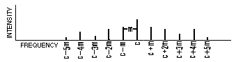
If the modulating signal is 8 Hz or lower, the result of the modulation is a vibrato, whereas above about 20 Hz, the TIMBRE of the tone is changed. In between these two frequencies, a transition from one effect to the other occurs. If the carrier consists of other PARTIALs, then pairs of sidebands are produced about each of them, creating a much more complex spectrum. Generally, the process is used for timbral synthesis.
The strength of the sidebands depends on the MODULATION INDEX, which is the ratio of the amplitude to the frequency of the modulating signal. (Note that the amplitude of the modulating signal equals the maximum frequency deviation Df of the resulting wave.) That is, the stronger the amplitude of the modulating signal, the greater the number of sidebands which contribute significantly to the spectrum. Mathematically, the amplitude of the nth sideband is given by the nth order Bessel function for the given modulation index.
Time-dependent spectra may be produced by varying the modulation index during the course of the sound. Most percussion-like sounds are characterized by a strong spectrum activated during the ATTACK, which then dies away during the DECAY; this may be approximated by a sharp rise in the modulation index followed by a slower decay. The time behaviour of the index, therefore, controls the spectral envelope of the sound (see SPECTRUM).
Ref.: J. Chowning, "The Synthesis of Complex Audio Spectra by Means of Frequency Modulation," Journal of the Audio Engineering Society, vol. 21, pp. 526-34, 1973.
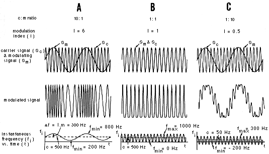
Three examples of frequency modulated signals, where (A) the carrier frequency is higher than the modulating frequency (c:m = 10:1), (B) both frequencies are equal, and (C), the modulating frequency is higher than the carrier (c:m = 1:10). The graph below each modulated signal shows the instantaneous frequency during the course of the modulation. Negative frequencies as shown may be considered as equivalent to positive frequencies with a phase shift of 180°.
Sound
Example: FM example A (above).
Sound Example: FM example B (above).
Sound Example: FM example C (above).
For a more detailed account of the properties of FM spectra, consult the FM Tutorial.
The amount or quantity of deviation a modulating or program signal causes a particular parameter of a CARRIER signal.
See: AMPLITUDE MODULATION, FREQUENCY MODULATION, MODULATION.
The process of separating the original information or SIGNAL from the MODULATED CARRIER. In the case of AMPLITUDE or FREQUENCY MODULATION it involves a device, called a demodulator or detector, which produces a signal corresponding to the instantaneous changes in amplitude or frequency, respectively. This signal corresponds to the original modulating signal.
In radio TRANSMISSION this process is a major function of a RECEIVER, in order to retrieve the desired signal.
See: HETERODYNE, RADIO SPECTRUM.
Any process in which the output depends functionally on itself (i.e. on the input). Feedback may be positive or negative; positive when the SIGNAL feedback is in PHASE with the input signal, and negative when it is in phase opposition (i.e. out of phase) with the input. Positive feedback is normally undesirable for AMPLIFIERs, for while the GAIN is increased, it is usually at the expense of stability and FIDELITY. Negative feedback, while cancelling part of the input, improves FREQUENCY RESPONSE, lowers DISTORTION and NOISE.
Feedback also refers to a process of behaviour modification in which information received about the behaviour and its effect influences future behaviour. This concept plays an important role in the field of cybernetics, and has influenced the design of servomechanisms, theories of learning, and work in artificial intelligence and computing science, among others.
In a similar sense, feedback can describe the process by which an individual receives acoustic information about the environment, information which is used for orientation with respect to it. Lack of acoustic feedback (in the sense of reflected sound) as experienced in an ANECHOIC CHAMBER may explain reactions of fear and disorientation that are reported.
See: communication, ECHOLOCATION, HI-FI, LO-FI, SONAR.
In TAPE MUSIC, tape feedback refers to a technique where the output of the playback head of a tape recorder is connected in the same circuit as the input to the recording head. A multiple ECHO is produced, provided there is a delay between the two heads, as there is on a machine where the heads are separate. When there is no delay, an effect similar to ACOUSTIC FEEDBACK is produced. Digital delay units allow the output signal to be recirculated into the input to produce a similar kind of feedback or multiple echo.
Compare: SOUND-ON-SOUND, TAPE ECHO, TAPE LOOP.
Sound
Example: B.C. ferry horns with 0.25 sec. feedback delay creating
multiple echoes.
Also called flanging or flangeing. An effect created by adding together two identical SIGNALs separated by a very short time delay (less than 25 ms, but strongest below 10 ms). These short delays are within the audio WAVELENGTH range, and the combination of the two signals affects the frequency SPECTRUM of the composite sound.
Because different frequencies have unique wavelengths, there is a different time or PHASE delay for different frequencies. For example, a time delay of 1 millisecond causes a 360° PHASE DIFFERENCE in a 1 kHz wave, but only a 180° phase difference for a 500 Hz wave. Thus CANCELLATION will occur at 500 Hz. In practice, cancellation is not complete but results in a drop of about 20 dB.
See: INTERFERENCE, PHASE-SHIFT, PINNA.
For two signals of amplitude A and frequency f, the resulting combined amplitude Ar, where the time delay between them is t, is given by:
Ar = A . /2 cos (2pft)/
The resulting amplitude will be at its lowest when ft = n/2, n = 1,3,5,7,...
For example, with t = 1 ms, cancellation in a complex spectrum will occur at 500, 1500, 2500, 3500,..... Hz. The effect is similar to that of a COMB FILTER at these frequencies. The resulting colouration is described as a 'swishing' or 'jet-like' sound, and is often heard on commercial recordings. The time delay, however, is seldom constant in practice, and so there will seem to be a rising and falling pitch as well. The pitch heard corresponds to a frequency whose PERIOD equals the time delay. It is more pronounced when the reflected sound is stronger or there are multiple reflections with the same delay.
The effect may be heard environmentally when a broad band noise is combined with its reflected sound (as with a passing car or plane). The resultant filtering is heard as a change in TIMBRE because the time delay is changing as a result of the speed of movement. See: GROUND EFFECT.
Sound
Example: Environmental phasing of the sound of a seaplane taking off
where the delayed signal occurs because of the strong REFLECTION off the water.
For long time delays, the ear can distinguish the two signals, as in (tape) ECHO. As the delay becomes shorter, the two signals are indistinguishable and a simple type of REVERBERATION effect is perceived. Phasing occurs with still shorter time delays.
Tape recorded sounds can be phased by recording and combining the playback of two versions of the same material on identical tape decks with close but not exact synchronisation. In the past, a common means of obtaining this effect with tape, called flanging, referred to a manual pressure exerted on the flanges of the tape reel causing it to run at a slower speed. This method introduced a fluctuating time delay, loosely referred to as flanging, whereas it is more properly termed phasing, with flanging being the method used to obtain it. Today, phasing is most commonly produced with digital delay units which allow very precise delays to be specified and modulated.
Compare: BEATS, BINAURAL HEARING, DISTORTION, DOPPLER SHIFT, FEEDBACK, PRECEDENCE EFFECT, SOUND-ON-SOUND.
Sound
Example: White noise with flanging produced by decreasing the time
delay between the original and the delayed signal.
Phasing also refers to a matching of phase, as with loudspeakers, which normally should be in phase with each other. See: QUADRAPHONIC.
A FILTER which passes the entire frequency range except for a set of very narrow BANDs, spaced usually at equal distances (on either a linear or logarithmic scale). The roll-off at each of these frequencies is quite sharp, giving a diagram of the response of the filter the shape of a comb. A comb filter effect is found in PHASING (also called flanging) and in PINNA reflections.
Sound
Example: A dynamically changing comb filter effect found in the
environmental phasing of the sound of a seaplane taking off.
A sound, usually high-pitched, caused when sound waves are picked up by a MICROPHONE from a loudspeaker connected in the same circuit as the microphone. The particular sound heard is a result of the RESONANCE characteristics of the circuit and the acoustic environment.
Compare: FEEDBACK, PHASING, SPILL.
A cathode ray electronic instrument by which the WAVEFORM of a sound or vibration may be observed. It displays an audio SIGNAL in the form of a transverse wave (as with all the diagrams of waveforms in this document, see SOUND WAVE).
Since sound pressure variations are shown as voltage variations, the AMPLITUDE of the signal may be measured and converted to DECIBELs with the aid of Appendix D.
DISTORTION of the waveform may also be observed, and in the case of a fixed waveform, its PERIOD and FREQUENCY may be measured.
Compare: LEVEL RECORDER, SOUND ANALYSER, SPECTROGRAPH, VU METER.
Any grouping of electronic equipment intended for SOUND SYNTHESIS. Such equipment usually incorporates a combination of OSCILLATORs, FILTERs, MIXers, ENVELOPE generators, white noise generators, SWITCHes, REVERBERATION units, etc. The term is now generally applied to digital sound synthesizers as well as their analog antecedents.
Such equipment became popular in the early 1960s, the major types of which were those created by Donald Buchla (the Buchla Box), Robert A. Moog (the Moog synthesizer), Peter Zinovieff (the Putney and Synthi synthesizers), and ARP Corporation (the ARP synthesizer). Since then many types of smaller and larger synthesizers have entered the commercial market as their use has become popular in ELECTRONIC MUSIC studios, classrooms, and among professional musicians.
Compare: MUSIQUE CONCRETE, SOUND OBJECT, TAPE MUSIC.
All analog synthesizers use the principle of voltage control to determine the values of the various sound PARAMETERs, and much of the use of a synthesizer involves the production, transformation and application of control voltages to units such as oscillators (to control frequency), amplifiers (to control amplitude), filters (to control cut-off frequencies and/or CENTRE FREQUENCY and BANDWIDTH), and mixers (to control amplitude of an input signal being mixed).
See: DIRECT CURRENT, RECTIFICATION, SUBAUDIO.
Sequences of control voltages may be produced by a keyboard or by a sequencer where the voltages are pre-set and then generated in a fixed sequence. The abbreviations VCO, VCA and VCF are used to describe voltage-controlled oscillators, amplifiers and filters, respectively.
See also: AMPLITUDE MODULATION, FREQUENCY MODULATION, GRANULAR SYNTHESIS.
Digital synthesizers utilize techniques of digital SOUND SYNTHESIS, ranging from those which implement specific synthesis algorithms, to those (called samplers) based on reproducing digitally sampled sounds, to those which are programmable and therefore can implement a variety of digital signal processing (DSP) techniques. Increasingly, however, stand-alone hardware digital synthesizers (other than keyboards and the like) are being replaced by systems implemented in software on general-purpose computers. See: DIGITAL RECORDING.
The electronic production of sound where no acoustic source is used. An electrical SIGNAL is produced which is the analog of a SOUND WAVE; that is, the voltage fluctuation in the signal represents that of the desired SOUND PRESSURE variation. When this signal is fed to an AMPLIFIER and LOUDSPEAKER, the sound becomes an acoustic signal which behaves like any other sound.
Electronic equipment which can synthesize sound is often grouped into large units called SOUND SYNTHESIZERs. Some of these are designed for speech synthesis, but most are for ELECTRONIC MUSIC purposes. Before the advent of the synthesizer in the early 1960s, a body of techniques called classical studio technique developed other methods of sound synthesis:
Compare: MUSIQUE CONCRETE, SOUND OBJECT, TAPE MUSIC, TAPE RECORDER. See also: HETERODYNE.
A process called digital sound synthesis can also be used to produce sound by means of a computer. The computer is programmed to generate numbers or samples which describe the pressure function of the desired sound. These numbers are converted into voltage steps by a digital-to-analog converter (DAC), and subsequently smoothed into a continuous signal by a low-pass FILTER.
The number of samples per second that are produced to describe the sound signal is called the sampling rate. Its value determines the BANDWIDTH of the SPECTRUM which may be generated, since only frequencies less than or equal to half the sampling rate may be produced without a kind of distortion called foldover. Thus, a minimum of 40,000 numbers/second is required to reproduce audio frequencies up to 20 kHz. To account for the roll-off of the low-pass filter, standard sampling rates are 44.1 and 48 kHz. Each binary digit (or bit) used to represent the sample adds 6 dB to the DYNAMIC RANGE of the signal.
Digital sound synthesis is termed real-time when the samples are calculated at the same time as the sound is heard, or with a very short intervening delay. When the process involves intermediate storage of the samples (on digital MAGNETIC TAPE, for instance), the process is termed non-real-time.
See: DIGITAL RECORDING, DUBBING, GRANULAR SYNTHESIS. Compare: TRANSDUCER.
Ref.: M.V. Mathews, The Technology of Computer Music, The MIT Press, 1969; C. Roads, The Computer Music Tutorial, The MIT Press, 1996.
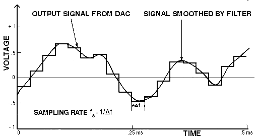
Production of a sound signal by digital synthesis. Numbers stored in the computer's memory are converted to discrete voltage steps by a digital-to-analog converter at fixed time intervals Dt, as shown above, along with the resultant signal smoothed by a low-pass filter.
A machine for converting one form of energy into another. An electronic generator usually converts DIRECT CURRENT (DC) power into ALTERNATING CURRENT (AC) power.
Also called an OSCILLATOR, when referring to an audio WAVEFORM generator used for SOUND SYNTHESIS. See: white noise.
Compare: AMPLIFIER, PULSE, RECTIFICATION, TRANSDUCER.
An electroacoustical device used to generate SIGNALs with specific WAVEFORMs. Oscillators are used, for example, to test electronic circuits, to transmit radio signals, and to provide compositional material in the production of ELECTRONIC MUSIC and SOUND SYNTHESIS.
Common types of oscillators are SINE WAVE, SQUARE WAVE, PULSE wave, TRIANGLE WAVE and SAWTOOTH WAVE oscillators, each distinguished by the shape of the waveform it produces. Oscillators can be simulated digitally by storing one CYCLE of the waveform and repeating those values during sound synthesis.
Compare: AMPLIFIER, GENERATOR, RESONATOR, SOUND SYNTHESIZER, TRANSDUCER.
A device used to open or close an electrical circuit. Also an electronic device used to alternate between two input SIGNALs, in some cases the rate of switching being controllable by a PULSE or triggering voltage.
Rapid switching of the on/off variety is called chopping, and can be effected by using a voltage-controlled amplifier (VCA) triggered by a PULSE WAVE or SQUARE WAVE.
See: ELECTROACOUSTIC, SOUND SYNTHESIZER. Compare: PEAK CLIPPING, RECTIFICATION.
The collection and study of verbal accounts of past events by individuals who have experienced them. The source material is normally recorded with a TAPE RECORDER and later transcribed into written form, a procedure first begun at Columbia University in the late 1940s. Collections of such transcriptions are often housed in local, regional and national archives or in the records of historical societies.
Similar techniques to record descriptions of remembered sounds, called EARWITNESS accounts, are used in SOUNDSCAPE studies. A recent evolution in the traditional concept of oral history has been termed aural history in order to shift the emphasis from the transcript as a final document to the sound itself as recorded on tape. Thus, aural history involves the creation of a document in sound which, by virtue of being tape recorded, is historical as soon as it is made. Sound so preserved may be of several kinds:
All of these have historical value, and are often made with the intent of preservation for later use, such as for research, broadcast, public presentations of all kinds, as well as for educational purposes. The first centre with this emphasis was the Aural History division of the Provincial Archives in Victoria, B.C., established in the early 1970s.
See also: DISAPPEARING SOUND, SOUND ROMANCE, TAPE RECORDING. Compare: PHONEMICS.
Ref.: Sound Heritage, Aural History, Provincial Archives, Victoria, B.C.
Musical compositions created with TAPE RECORDERs and MAGNETIC TAPE using a variety of sources, both electronic and natural. Activities in tape music began in both Europe and America after the Second World War. See: TAPE RECORDING.
Various techniques such as SPLICING, TAPE LOOPs, tape ECHO, SOUND-ON-SOUND, tape FEEDBACK, speed changes, tape reversal and MIXING are used in the making of this kind of music, all of which are usually simulated by contemporary digital editing techniques.
Compare: DIGITAL RECORDING, ELECTRONIC MUSIC, MUSIQUE CONCRETE, SOUND SYNTHESIS. See: DIFFUSION.
(French: concrete music) A development introduced in Paris in 1948 by Pierre Schaeffer at the studio of the French Radio (O.R.T.F.). Its aim was to replace traditional musical material with recorded (i.e. concrete) sounds which were then manipulated by FILTERing, tape reversal, TAPE LOOPs, speed changes, tape SPLICEs, or other electronic means. The source of all sounds, however, was environmental. The experimental side of this study developed the concept of l'objet sonore (see SOUND OBJECT).
Compare: DIGITAL RECORDING, ELECTROACOUSTIC, ELECTRONIC MUSIC, SOUND EFFECT, SOUND SYNTHESIS, TAPE MUSIC, TAPE RECORDER, TAPE RECORDING.
Strictly speaking, electronic music refers to the production and treatment of sounds exclusively by electronic means such as OSCILLATORs, FILTERs and MODULATORs. See: SOUND SYNTHESIS, SOUND SYNTHESIZER.
Electronic music grew out of the activities in Europe in the 1950s of composers at the Cologne and Milan studios of the German and Italian Radios. Independent research in the United States and Canada at about the same time resulted in the creation of studios at Columbia University, the University of Toronto and elsewhere.
Today, 'electronic music' is a general term used to refer to any music produced by ELECTROACOUSTIC or other electronic means.
Compare: MUSIQUE CONCRETE, TAPE MUSIC. See: DIFFUSION, DIGITAL RECORDING, QUADRAPHONIC.
The device, successor to the MAGNETIC WIRE recorder, which since the 1940s (when it was called the sound mirror) has been the most commonly used means of storing and reproducing an AUDIO signal. Today, the Digital Audio Tape (DAT) recorder has replaced the older reel-to-reel machines in many studios (see DIGITAL RECORDING, MAGNETIC TAPE).
In an analog tape recorder, the electrical input SIGNAL, from a MICROPHONE for instance, is imprinted onto magnetic tape where the variation in current is stored as a variation in magnetic polarity of the oxide particles on the tape (see diagrams under EMULSION). The transferral of the acoustic signal to a material form has held great consequences for analysis and composition in the way it allows repetition, storage and transformation of the original sound.
See: MUSIQUE CONCRETE, ORAL HISTORY, SCHIZOPHONIA, TAPE MUSIC, TAPE RECORDING. Compare: GRAMOPHONE, SOUND SYNTHESIS.
As well, the tape recorder is an essential tool for SOUNDSCAPE studies, in that environmental sounds may be recorded and preserved (of particular importance with DISAPPEARING SOUNDs), thereby allowing their analysis and study at a later date. Such sound recordings may also be used compositionally to elucidate aspects of the soundscape, such as by isolating, juxtaposing or mixing certain rhythms, timbral qualities, or other acoustic patterns in ways that do not normally occur. These techniques explore sound association, MORPHOLOGY and symbolism in the sense that form and meaning are constantly derived from new relationships.
For other aspects related to analog tape recording see: BULK ERASER, CROSSTALK, DIFFUSION, DROPOUT, DUBBING, EMULSION, EQUALIZATION, FLUTTER, MIXING, MONTAGE, PHASING, PRINT-THROUGH, SOUND-ON-SOUND, SPLICE, tape ECHO, tape FEEDBACK, TAPE LOOP, TEMPOPHONE, TRACK, VU METER, WOW.
The process of using a TAPE RECORDER for the storage of sound on MAGNETIC TAPE, or the information stored by this process.
See also: EMULSION, ORAL HISTORY, MUSIQUE CONCRETE, STEREOPHONIC, TAPE MUSIC, TRACK.
Although tape recording became generally used in North America in the late 1940s, the following list outlines some of the first developments previous to that, as well as some recent innovations:
A recent development where, in contrast to the conventional analog TAPE RECORDER, the audio SIGNAL is sampled within a set of pre-defined limits. It is thus the reciprocal process to that described as digital SOUND SYNTHESIS. Digital sampling is also used is some digital SOUND SYNTHESIZERs. See: TAPE RECORDING.
In a typical digital recorder the input signal is first FILTERed to remove any frequencies that cannot be accurately represented digitally. Then the instantaneous AMPLITUDE of the signal WAVEFORM is sampled at a rate at least twice as high as the highest frequency which remains after filtering (at least 40,000 times per second in the case of 20 kHz, for example). The sampling process results in a steady stream of instantaneous signal-waveform values (1/40,000 of a second or 25 microseconds apart for the instance quoted). The standard sampling rates for digital recording are 44.1 and 48 kHz. See: TRANSIENT RESPONSE.
An analog-to-digital converter (ADC) which performs this sampling process expresses these values as binary numbers, and it is this digital information, rather than the analog waveform itself, which is recorded on MAGNETIC TAPE, computer memory or other storage medium. The playback process recovers the numbers from the storage medium (see diagrams under MAGNETIC TAPE and SOUND SYNTHESIS). Compare: TRANSDUCER.
When a digital signal is copied, there is no increase in NOISE or added DISTORTION, provided no errors have occurred. The opposite is true in analog to analog DUBBING of magnetic tape. A second major advantage of digital recording is that a DYNAMIC RANGE in excess of 90 dB can be achieved with 16-bit samples, whereas with analog techniques, the available range, and therefore the maximum SIGNAL-TO-NOISE RATIO, rarely exceeds 60 dB. Finally, since individual samples may potentially be accessed, editing is considerably more accurate than that achieved with the usual tape SPLICE, although it must be performed with the use of software, not manually.
See: VU METER. Compare: BINAURAL RECORDING, ELECTRONIC MUSIC, MUSIQUE CONCRETE, TAPE MUSIC.
A pre-recorded or simulated sound produced for a radio, television, film or theatrical program in order to suggest an actual sonic environment. The design of such sounds (often abbreviated as SFX), particularly when a complex acoustic environment is to be simulated, involves a thorough understanding of the structure of such a SOUNDSCAPE; that is, what sounds are representative and most significant, as well as which are necessary to create a given AMBIENCE and sense of ACOUSTIC SPACE.
Because the best sound effects are, like the cinematic music score, only subliminally perceived, an understanding of the audience's acquaintance with sounds - i.e. their skills and limitations in aural perception and cognition - is also of considerable importance.
A skillful sound effects producer or Foley artist can give the listener a vivid mental impression of a soundscape by carefully selecting and balancing only those sounds necessary to create the appropriate effect. To do this well means not only to know which sounds are prominent in the environment, but which are also prominent in the memory of those experiencing it, since a listener selects only certain sounds for long-term memory and rejects all others, even when they may be louder.
Compare: MUSIQUE CONCRETE, SOUND OBJECT, SOUND EVENT, SOUND ROMANCE, SOUNDSCAPE DESIGN, SOUND SIGNAL.
Ref.: Alan Edward Beeby, Sound Effects on Tape, London, 1966.
Pierre Schaeffer, with whom the French version of this term (l'objet sonore) is most associated, describes it as an acoustical "object for human perception and not a mathematical or electroacoustical object for synthesis." The sound object may be defined as the smallest self-contained element of a SOUNDSCAPE, and is analysable by the characteristics of its SPECTRUM, LOUDNESS and ENVELOPE.
See also: GRAIN, INTERNAL DYNAMICS, MASS, TIMBRE, VOLUME.
Though the sound object may be referential (e.g. a bell, a drum, etc.) it is to be considered primarily as a phenomenological sound formation, independent of its referential qualities as a SOUND EVENT. Schaeffer: "The sound object must not be confused with the sounding body by which it is produced," for one sounding body "may supply a great variety of objects whose disparity cannot be reconciled by their common origin." Similarly, the sound object may be considered independently of the social or musical contexts in the soundscape from which it is isolated. Sound objects may be classified according to their MORPHOLOGY and TYPOLOGY.
Recording and processing a sound object is often the starting point for ELECTROACOUSTIC music composition.
See also: MUSIQUE CONCRETE, TAPE LOOP. Compare: SOUND EFFECT, SOUND SIGNAL, SOUND SYNTHESIS.
Ref.: P. Schaeffer, Traité des Objets Musicaux, Paris, 1966; and Trois microsillons d'exemples sonores, 3 discs and booklet, published by l'O.R.T.F., Paris.
A sound or sound sequence in its spatial and temporal context as part of a SOUNDSCAPE. Whereas the SOUND OBJECT is abstracted from its original context and exists only as an acoustical object for study, the sound event acquires its meaning through its social and environmental context, as well as from its own acoustic characteristics.
Therefore, an acoustic description of the sound event includes its AMBIENCE, its relation to that ambience (see HI-FI, KEYNOTE, LO-FI, SOUND POLLUTION), as well as other environmental features (including REVERBERATION), ACOUSTIC SPACE and RHYTHM. Sound events may be classified according to their semantic, symbolic or structural functions or qualities (see MORPHOLOGY, TYPOLOGY).
Compare: SOUND EFFECT, SOUND SIGNAL.